According to ASGE data, U.S. clinicians performed over 22 million GI endoscopic procedures in 2019 alone — a figure that reflects just how central these instruments are to modern diagnosis and treatment.
This guide is written for clinicians and endoscopy staff who want a functional understanding of each component, biomedical technicians responsible for scope maintenance, and healthcare facility managers making procurement or equipment upgrade decisions. By the end, you'll know what every major part does, why it matters, and how component wear affects clinical performance and equipment lifecycle decisions.
Key Takeaways
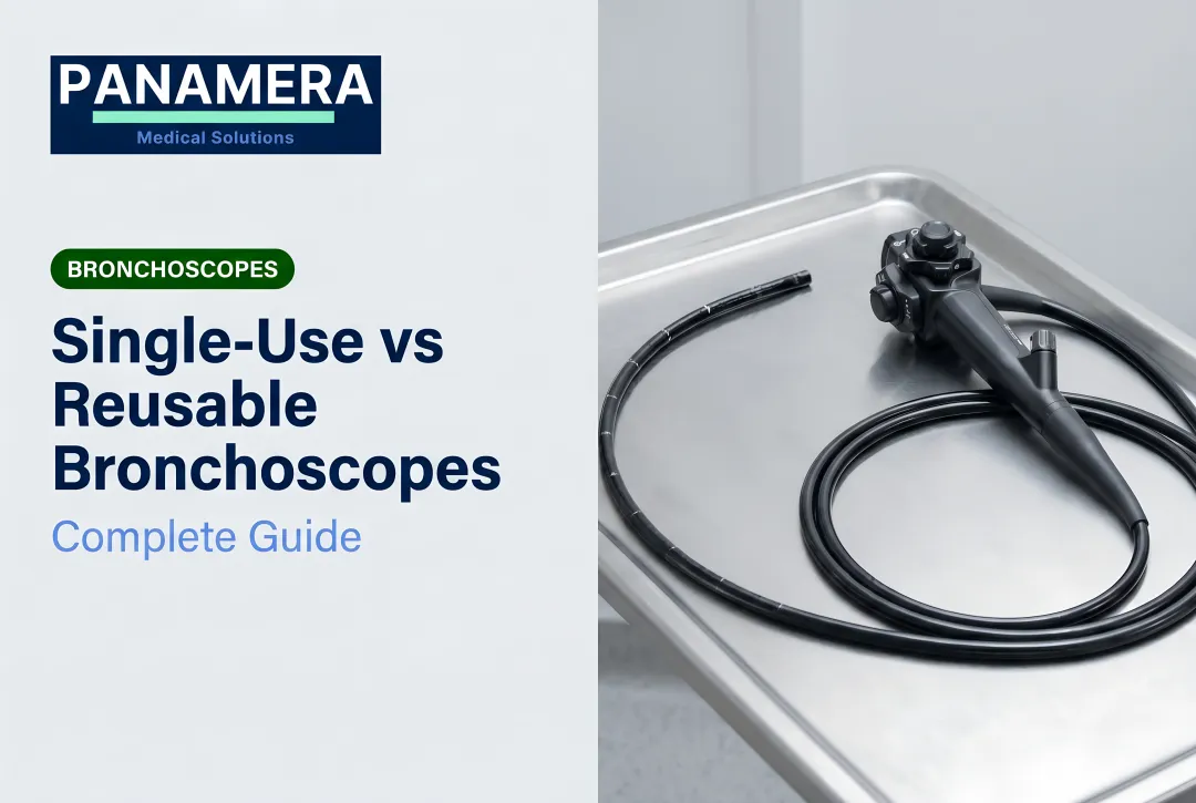
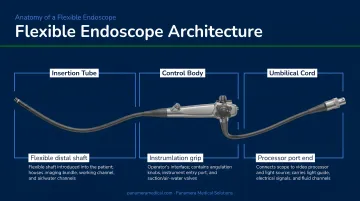
- A flexible endoscope divides into three primary sections: the insertion tube, the control body (handpiece), and the umbilical cord/connector
- The distal tip houses the most critical components — the objective lens, light guides, air/water nozzle, and instrument channel opening
- The bending section is the most mechanically stressed part — 36% of scope leaks originate there
- Deflection wheels control tip angulation via traction wires — wire slack or breakage is a leading cause of angulation failure
- Tracking component wear helps facilities determine when repair costs exceed a scope's remaining service life
The Three Main Sections of a Flexible Endoscope
Every flexible endoscope — across every brand and clinical application — shares the same fundamental architecture: three physically connected sections that function as one integrated system.
The insertion tube is the part that enters the patient. It carries all internal channels (air, water, suction, instrument, and light guides) and terminates at the working end of the scope.
The control body (handpiece) is held by the operator throughout the procedure. It houses the deflection wheels, suction and air/water valves, accessory channel port, and remote video controls.
The umbilical cord runs from the handpiece to the light source and video processor. It acts as the supply conduit, carrying light, air, water, suction, and electrical signals between the scope and the external equipment stack.
Every action at the handpiece transmits directly to the distal tip through components running the full length of the instrument. Each section has a distinct role:
| Section | Primary Function |
|---|---|
| Insertion tube | Mechanical navigation + optical/fluidic delivery |
| Control body | Operator interface — steering, suction, air/water |
| Umbilical cord | Supply conduit — light, fluids, electrical signals |
For biomedical technicians: while this architecture is consistent across Olympus, Pentax, and Fujifilm platforms, component placement and connector designs differ by brand — a distinction that matters when servicing multi-brand fleets.
The Insertion Tube: Flexible Shaft, Bending Section, and Distal Tip
Flexible Shaft
The flexible shaft is the long tubular body of the scope that travels through the patient's anatomy. It transmits push, pull, and torque forces from the operator's hand down to the tip, while housing every internal channel in a compact, layered structure. Think of it as the scope's backbone and cable conduit in one.
The shaft must balance two competing demands: enough flexibility to navigate curves without patient injury, and enough column strength to advance without collapsing. Modern colonoscopes address this through variable stiffness technology, which lets the operator dial up shaft rigidity on demand to prevent looping.
A meta-analysis of 2,033 patients found that variable-stiffness colonoscopes improved cecal intubation rates versus standard adult colonoscopes. In cases where a standard scope had already failed, a variable-stiffness colonoscope achieved a 94% completion rate — demonstrating that shaft mechanics directly affect clinical outcomes, not just operator comfort.
Bending Section
Just proximal to the distal tip sits the bending section: the articulating segment that gives the scope its steering capability. It consists of linked metal rings connected by traction cables running back to the deflection wheels on the handpiece. Pulling a cable causes the tip to deflect in the corresponding direction — up, down, left, or right.
Cable tension determines how faithfully the tip responds. Research on clinically used endoscopes found that most instruments did not reach their maximal prescribed bending angles, with some deviating by up to 50 degrees. Insufficient tension causes delayed, unresponsive tip movement; excessive tension increases friction and accelerates wear.
That accumulated wear makes the bending section the most failure-prone area of the scope. Olympus repair data identifies it as the origin of 36% of common leaks — typically from cracked rubber sheaths that allow fluid ingress during procedures or reprocessing.
What drives bending section wear:
- Repeated high-angle deflection cycles fatigue the rubber sheath over time
- Overtightened cables create friction that erodes internal components
- Inadequate post-procedure inspection allows small cracks to progress undetected
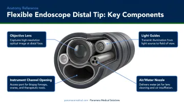
Distal Tip
The distal tip is where clinical work actually happens. Every element at this end has a specific job:
- Objective lens — captures the image; scratches or cracks directly degrade visualization
- Light guide lenses — transmit illumination from fiber bundles or LED emitters to the mucosal surface
- Air nozzle — delivers insufflation to open the lumen for visualization
- Water nozzle — flushes the objective lens to clear debris mid-procedure
- Instrument/suction channel opening — the portal through which biopsy forceps, snares, and other accessories emerge (at the 5 o'clock position in colonoscopes, 7 o'clock in gastroscopes, per endoscopic view)
Tip damage — cracked lens covers, blocked nozzles, damaged channel mouth — is among the most common reasons scopes require repair. Olympus operation manuals specifically require inspection of the distal objective lens and light-guide lenses for scratches, cracks, and staining before each use.
The Control Body: Handpiece Controls and Valves
Deflection Wheels and Locks
The handpiece carries two deflection wheels. The large wheel controls up/down tip angulation; the small wheel controls left/right movement. There's a counterintuitive ergonomic detail that catches new trainees: due to optical orientation, turning the large wheel downward actually angulates the tip upward in endoscopic view. Internalizing this is part of developing efficient technique.
Each wheel has a locking mechanism ("F" knobs) that fixes the tip in position — useful when the operator needs both hands free during targeted biopsy or therapeutic intervention.
Mastery of the two-wheel system, often combined with simultaneous shaft torquing, defines experienced endoscopic technique. Pentax service documentation notes that knob play exceeding 30 degrees without corresponding distal tip movement indicates angulation system wear — a practical diagnostic threshold for biomedical technicians.
Air/Water and Suction Valves
The blue air/water valve has two functions controlled by depression depth:
- Partial depression (covering the vent hole) delivers air to distend the lumen
- Full depression flushes water across the objective lens
The red suction valve aspirates fluid, blood, and debris through the instrument channel when depressed. The biopsy cap over the accessory port must be properly seated for the suction system to generate adequate negative pressure — a simple step that's easy to overlook mid-procedure.
Some scope models also include a forward water jet connector, which delivers high-pressure irrigation directly from the distal tip without occupying the instrument channel. This matters most during therapeutic procedures when an accessory is already deployed in the channel.
Accessory Channel and Remote Controls
The accessory/biopsy port on the handpiece is the entry point for all diagnostic and therapeutic tools. A rubber biopsy cap seals this opening to maintain suction integrity. Common instruments passed through this port include:
- Biopsy forceps
- Polypectomy snares
- Injection needles
- Hemostatic clips
- Cytology brushes
Therapeutic endoscopes designed for complex cases (such as GI bleeding) may carry two accessory ports, allowing simultaneous deployment of two instruments.
The handpiece also carries 2–4 remote video buttons (brand-dependent) for image capture, video recording, and toggling advanced imaging modes like narrow-band imaging (NBI). These keep the operator at the handpiece without reaching for the processor panel.
The Umbilical Cord and Connector Head
The umbilical cord runs from the handpiece to the light source and video processor. Inside its flexible outer jacket, it houses multiple distinct conduits running in parallel:
- Light guide fiber bundle (or electrical cable in video scopes)
- Air and water supply tubes
- Suction channel
- Electrical signal wires connecting the image sensor to the processor
At the terminal end sits the connector head — sometimes called the PVE connector or light guide plug. This component connects the scope to three external systems simultaneously: the light source, the video processor, and the air/water/suction supply ports.
The connector head also contains the leak test port, ground wire contacts, and (in Pentax scopes) the water bottle connector. The electrical contact pins are moisture-sensitive and require a waterproof soaking cap during reprocessing.
Connector handling varies by manufacturer, and the differences are not interchangeable:
- Olympus warns against hitting or bending the electrical contacts, as damaged pins impair light source connection
- Pentax cautions that the metal light-guide plug and electrical pins may be hot immediately after use
- Fujifilm separates the CCD connection seat from the guide head on some platforms
Technicians managing multi-brand fleets should keep manufacturer-specific handling notes accessible at the reprocessing station — connector damage from incorrect handling is one of the more avoidable repair costs in endoscope maintenance.
Imaging Systems and Working Channels
Imaging: Fiberoptic vs. Video
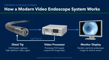
Two imaging technologies exist in clinical use. Fiberoptic scopes transmit the image via coherent fiber bundles from the objective lens to an eyepiece or external camera head. They're older technology, still found in some facilities, but have largely been superseded.
Video endoscopes — the current standard — place a CCD or CMOS image sensor directly at the distal tip. The sensor converts the optical image to an electronic signal, transmitted through the umbilical cord to the video processor for display on a monitor. Compared to fiberoptic systems, they offer superior resolution, accurate color reproduction, digital documentation, and simultaneous multi-viewer access.
Modern video platforms extend further with advanced imaging modes:
- Narrow-band imaging (NBI) enhances mucosal surface contrast to highlight vascular patterns
- i-scan provides detailed surface topography that can influence endoscopic management decisions
- High-definition and 4K systems increase image detail at the hardware level
These capabilities are hardware-dependent — they require specific imaging chips and compatible light sources. For facilities evaluating an upgrade, this hardware dependency is the key distinction between older and current-generation equipment — a scope replacement often requires a compatible processor as well. Panamera Medical Solutions sources complete video system sets (such as Olympus CV-190/CLV-190 and Fujifilm VP-7000/BL-7000 combinations) alongside individual scopes to address exactly this scenario.
Working Channels: Air, Water, Suction, and Instrument
Four internal channel systems run the length of the insertion tube:
- Air channel — connects from the processor's air pump to the distal air nozzle for lumen insufflation
- Water channel — supplies lens-washing fluid to the distal tip
- Suction/instrument channel — the largest lumen; serves dual duty as the aspiration pathway and the conduit for accessories
- Auxiliary water jet channel — present on select models; delivers high-pressure irrigation independently of the instrument channel
The suction/biopsy channel carries the highest contamination risk in the entire scope. Its size, direct exposure to body fluids, and complex internal geometry create conditions where biofilm can form — particularly on scratched or damaged channel liners.
Reprocessing compliance is non-negotiable here. Multisociety reprocessing guidance reports that inadequate drying is associated with 80% of contamination events, since residual moisture supports waterborne organisms. SGNA standards require brushing internal channels until no debris appears on the brush — a step that sounds straightforward but is where reprocessing failures most often occur.
Types of Flexible Endoscopes and Their Specialized Components
Different endoscope types are engineered for specific anatomical environments, and those environments place distinct demands on their components.
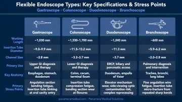
| Scope Type | Key Specs | Primary Stress Points |
|---|---|---|
| Gastroscope | Forward-viewing, ~9–11mm insertion tube | Objective lens, instrument channel |
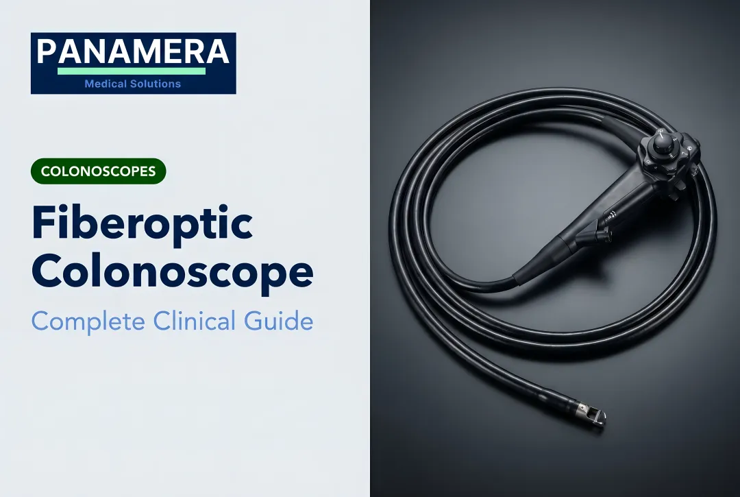
| Colonoscope | Long shaft, variable stiffness (e.g., Pentax EC34-i10L: 1700mm working length, 11.6mm diameter) | Flexible shaft looping stress, bending section wear |
| Duodenoscope | Side-viewing with elevator mechanism (e.g., Olympus TJF-Q190V) | Elevator mechanism — complex geometry, high contamination risk |
| Bronchoscope | Narrow, highly flexible (e.g., Olympus BF-Q190: 4.8mm distal OD, up to 210° upward angulation) | Tight angulation cycles, bending section fatigue |
| Cystoscope | Compact, urological access | Insertion tube flexibility, instrument channel |
The duodenoscope's elevator mechanism (a small hinged component at the distal tip used to direct guidewires during ERCP) has complex geometry that standard reprocessing protocols struggle to clean adequately. The FDA has documented an association between reprocessed duodenoscopes and multidrug-resistant organism transmission, including CRE outbreaks. Surveillance studies report 4.1% to 6.1% of duodenoscopes remaining contaminated with high-concern organisms even after high-level disinfection.
Understanding these component-level demands helps facilities anticipate repair cycles and recognize when a scope has reached the end of its cost-effective service life.
For aging fleets (colonoscopes with worn bending sections, gastroscopes past their service intervals, or older video platforms with outdated imaging chips), Panamera Medical Solutions' Trade-In and Buy-Back programs let facilities receive credit toward newer-generation equipment or a cash payment for unneeded scopes and video systems across Olympus, Pentax, Fujifilm, Karl Storz, and Stryker platforms.
Frequently Asked Questions
What are the main parts of a flexible endoscope?
A flexible endoscope consists of three primary sections: the insertion tube (which enters the patient), the control body or handpiece (held by the operator), and the umbilical cord with connector head (linking the scope to the light source and video processor). Each section contains distinct mechanical, optical, and fluidic subsystems.
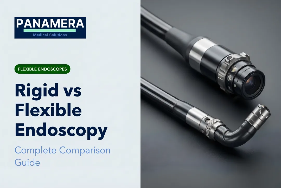
What functions are unique to flexible endoscopes compared to rigid endoscopes?
Flexible endoscopes navigate curved anatomy — the GI tract, bronchi, bile ducts — using an articulating bending section, while simultaneously delivering air, water, and suction and passing therapeutic instruments through the working channel. Rigid endoscopes cannot replicate these functions in curved or deep body cavities.
What body parts can be examined with a flexible endoscope?
Common examination areas include:
- Upper GI tract (esophagus, stomach, duodenum) — gastroscopy
- Large intestine — colonoscopy
- Airways and lungs — bronchoscopy
- Bile ducts and pancreatic duct — ERCP via duodenoscope
- Bladder and urethra — flexible cystoscopy
How does the bending section of a flexible endoscope work?
The bending section uses traction cables running from the deflection wheels on the handpiece to the articulating segment just proximal to the distal tip. Turning a wheel pulls its corresponding cable, causing the tip to deflect in that direction. Four cable directions enable up, down, left, and right movement.
What is the working channel of a flexible endoscope used for?
The working channel serves two simultaneous functions: it allows passage of diagnostic and therapeutic accessories (biopsy forceps, snares, injection needles) from the handpiece port to the distal tip, and it also functions as the suction channel to aspirate fluid, blood, or debris during the procedure.
How does component wear affect endoscope performance, and when should equipment be replaced?
High-wear components such as bending section sheaths, angulation wires, and working channel liners degrade with repeated use, leading to image loss, angulation failure, or infection risk. Facilities should follow manufacturer service intervals and consider trade-in or buy-back programs when cumulative repair costs exceed the scope's remaining functional value.